|
ShenzhenTimesStarlightTechnologyCo.,Ltd,
|
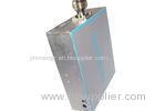
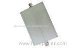
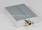
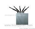
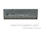
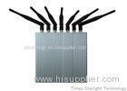
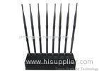
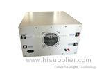
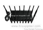
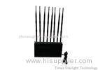
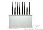
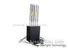
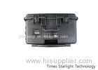
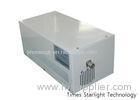
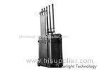
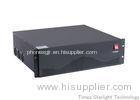
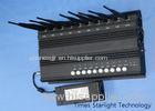
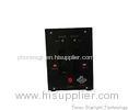
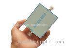
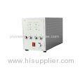
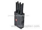
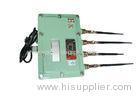
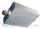
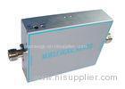
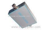
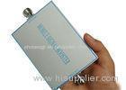
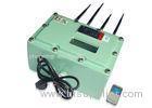
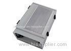
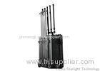
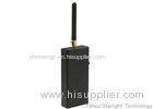
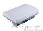
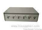
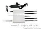
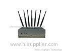
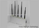
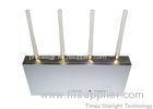
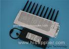
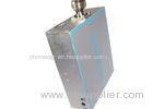
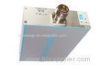
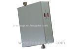
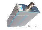
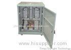
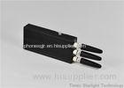
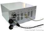
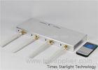
Household Portable Cell Phone Signal Booster Repeater Wifi With Dual Band
| Place of Origin: | Zhejiang, China (Mainland) |
|
|
|
| Add to My Favorites | |
| HiSupplier Escrow |
Product Detail
Household Portable Cell Phone Signal Booster Repeater Wifi With Dual Band <span style="font-fami
Household Portable Cell Phone Signal Booster Repeater Wifi With Dual Band
Line Amplifiers are specially designed to assist the Base Station (BTS) or Repeaters to compensate the system loss from in-building distributing cable, power splitter and directional coupler and extend in-building signal coverage, and improve flexible of in-building signal coverage system design to meet the field strength requirements of in-building signal coverage system.
Description
Indoor Signal Booster series is an ideal solution for small/medium businesses and home users looking to enhance indoor wireless connectivity. It is connected via coaxial cable to Donor Antenna and Service Antenna, Donor Antenna is placed outside the building where it has easy access to a BTS signal, and the Service Antenna is placed in the building where it can extend radio coverage to the blind area.
Features
1. Cost effective solution for weak signal zones, reduce drop/off calls.
2. Compact size, low power consumption, easy installation, great cover.
Expansion and extention of the signal of base station.
Optimization of the quality of the signal and source
3. Cover about 500~3000 m² without block or obstruct.
4. High linear design, ALC function design, low interference to BTS.
5. Support any cellular devices (voice & data & video)
6. Wide band signal booster, or customize selective band booster.
Antenna isolation testing,Prevent the oscillation
7. Support system CDMA450, LTE700, LTE800, iDEN, CDMA800/GSM850,
GSM900, EGSM, AWS1700, DCS1800, PCS1900,WCDMA, LTE2600,etc.
8. Aluminum-alloy IP65 casing has high resistance to dust, water and corroding;
9. High gain linear power amplifier technique with reliable performance
10. In-built AGC & ALC function be able to ensure easy installation without setting.
11. Compact size and light weight, easy to install on wall or pole
12. Adopting filter with highly selectivity and low insertion loss eliminates interference between uplink and downlink
13. Support SNMP and Web-based GUI.
14. RS232 or RJ45 ports provide links to laptop for local setting and monitoring by built-in web interface.
15. Built-in wireless modem (Option) for remote monitoring by SMS, GPRS or TCP/IP.
16. Details repeater parameters and status can be monitoring by built-in web interface, such as RSSI, temperature, output power level, gain, ATT, return loss, VSWR etc.
Standard Package
1. AC90-264V, DC9V/3A power supply adapter 1PCS
2. AC power cord (EU/US/UK/SA/China standard, etc) 1PCS
3. Installation kit 1PCS
4. User manual 1PCS
Recommended Accessories
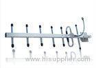
1. Donor antenna: Log Periodic Antenna (9dBi,806-960/1710-2700MHz)
2. Service antenna: Omni Ceiling Antenna (3dBi,806-960/1710-2700MHz)
3. 5D-FB coaxial cable with connecter (Cable length optional)
Application
To expand signal coverage or fill signal blind area where signal is weak or unavailable.
Outdoor: Airports, tourism regions, golf courses, tunnels, factories, mining districts, villages, highways
Indoor: Hotels, exhibition centers, basements, shopping malls, offices, parking lots.
| Item | Mobile Booster Repeater Wifi |
| Repeater type | Digital Filter Repeater (DFR), minimum 3 sub slot band |
| Frequency Work | 925 – 935 MHz |
| Input port repeater max | -55 dBm |
| Output port repeater max | 26 dBm |
| Gain max | 81 dB |
| Power Adjustment | 31 step / 1 dB |
| Isolation Min (dB) | 84 |
| Repeater type | Digital Filter Repeater (DFR), minimum 3 sub slot band |
| Frequency Work | 880 – 900 MHz |
| Input port repeater max | -65 dBm |
| Output port repeater max | 16 dBm |
| Gain max | 81 dB |
| Power Adjustment | 31 step / 1 dB |
| Isolation Min (dB) | 84 |
| VSWR | 1.1<=x<1.4 |
| Inter-modulation | Max -37dbm or -80dbc |
| Spurious Emission | Max -37dBm at +/- 750 kHz |
| I/O Impedance | 50 ohm |
| Noise Figure | Max 5dB |
| Group Time Delay | Max 4µS |
| Temperature Range | -25 degree Celsius to +55 degree Celsius |
| Relative Humidity | Max 95% |
| MTBF | Min. 100000 hrs |
| Connector Type | N-female |
| ICS | No |
| ALC | Yes |
| AGC | Yes |
| AGC Control Range | Min 40dB (+/-1dB) |
| Gain Control Range | 31 step (1dB Step) |
| NMS based on Data service (include modem (2G/3G or 2G only (GSM/DCS or GSM only)*)) | Yes |
| GUI | Yes |
| Power Consumption | 50 W |
| Power Supply Type | Switching Regulator |
| UPS with casing (IP 65, repeater inside) | Need |
| UPS Capacity | 4 hours |
| Antenna system (include accessories) | |
| Donor | |
| Type | Yagi (pig tailed N-female 30 cm) |
| Gain | > 18 dBi |
| Pole antenna (Ø 2" aluminium include bracket) | 4 meter |
| Serving | |
| Type | Sectoral |
| Gain | > 17 dBi |
| Pole antenna (Ø 5" aluminium include bracket) | 3 meter |
| Installation part | |
| Cable RG8 length | 30 m |
| Connector N-male RG8 | 2 pcs |
| MCB with box | 2 Amp |
| Power cable 3wire w/ stop contact | 10 meter |
| Installation local material (ties cable, rubber, isolatif 3M, sticker Isat, cable clamp etc) | 2 package |
Instructions on installation
1. Firstly, select an appropriate position to mount. The signal amplifier is better to be mounted close to walls. At the position selected, punch a hole in the wall as shown in the diagram and aim the bolt at the hole. Then fasten and fix with expansion bolts.
2. Connect the BTS Port with out door reverse antenna through radio frequency cable. In general, the reverse antenna is mounted at a higher position. Yagi antenna and panel antenna may be used. The main lobe of the antenna radiation is oriented towards the base station and the reverse antenna and base station antenna should be visible as possible.
3. Connect User’s Port with the ports of indoor covering system or indoor relay antenna. In general, the indoor covering system is composed of several splitters, couplers, expansion amplifiers and antennas and applied as per specific engineering design for the purpose of satisfying the signal covering demands in large area or complicated terrain indoor space. In the case of small area indoor space, the requirements for covering can be satisfied by using single relay antenna with the option of hanging antenna or ceiling antenna.
4. Finally, connect the power interface to 5V2A power adapter and power on the adapter with 220v AC. The signal amplifier installation is thus completed.

